Electrical connectors, are utilized in many different applications, where generally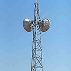 current is conveyed from a source to a use of power or grounding. Telecommunications involves many different application types in which connectors are used. Generally, telecommunications (telecom) are used in three broad business areas: Central Office, Outside Plant, and Mobility. Central Office refers to large facilities where very high volume communications are switched and processed. Outside Plant refers to switching stations where distributive switching occurs for commercial and home land lines. Mobility refers tower-based power and grounding to support mobile communication transmission. Generally, power is brought into these facilities to support reception and transmission and grounding connections serve to protect the systems from overload conditions, including lightning strikes.
Though there are a wide range of connector types, including “pin”, “fiber optic”, and other electronic low amperage Telecom Connectors, Telecom Connectors used in Power and Grounding connection fall into the categories of Compression Terminal Lugs and Compression Splices, with Terminal Lugs being used in the great majority of connecting applications. A review of our glossary will help the reader understand Terminal Lug and Splice features and characteristics.
Generally, these products are defined by the wire size they convey and the bolt or stud hole patterns that “terminate” the current to the power or grounding source. Telecom power cables run between 10 Gauge and 750 MCM in size (between 1/8” and 1 1/8”m copper conductor diameters). Telecom grounding cables run between 8 Gauge and 250MCM. Stud hole sizes are based upon a size of screw or bolt diameter appropriate to fix the terminal tang (flat area of terminal) to the power or grounding surface securely. Bolt holes are sized both to the geometry of terminal’s wire size, but also the mating surface/hardware of the source or use of power. In gauges,10 Gauge through 2 Gauge, 1/4” and 3/8” nominal stud holes (with 1/16” clearance typically). In larger gauges, from 1/0 through 750 MCM stud hole sizes are 3/8, 1/2 and 5/8”. The number of stud holes provided varies by the application involved. Where secureness needs are not optimal and “rotation” of the terminal enables the terminal to be terminated at varying angles to the bolted point, single hole terminals are used. Where secureness is important and/or where in-line, parallel positioning of terminated leads require straightness, double stud hole terminal designs are used. NEMA, National Electric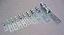 Manufacturer’s Association, a standard-setting body, has established spacing standards, which control the consistent distance between stud holes, resulting in pairs like 1/4" Holes on 5/8” Centers, 5/16” Hole on 3/4" Centers, 3/8” Holes on 1” Centers, and 1/2" Hole on 1” Centers.
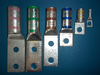
Telecom Terminals and Splices are color-coded to match with industry standard crimp tools color-coding such that field installation is guide to secure matched connectors and crimp tools by color-coding.

ASK’s Configurator will allow you to select the appropriate terminal lug, by wire size, stud hole option, color-code, and other criteria.


 1674 Frontenac Rd | Naperville, IL 60563